TVMounty installation guides
How to Plan a TV Mount in a Room Corner
Updated November 5, 2026
A TV can work in a room corner when the mount reaches the intended screen position, the entire TV clears both walls, and the attachment method suits the actual wall structure. Start with the TV's measured width, your viewing position, and the mount's installation drawing. A bracket's screen-size range or advertised swivel angle alone cannot tell you whether it will fit your corner. Check the parked position and the movement between positions before drilling.

Choose the screen position before the bracket
Sit where you normally watch and decide which direction the screen should face. A television does not have to sit symmetrically across a 90-degree corner. Angling it toward the main seats may be more useful than aligning it with the room's diagonal, particularly when the corner is beside a doorway or an open walkway.
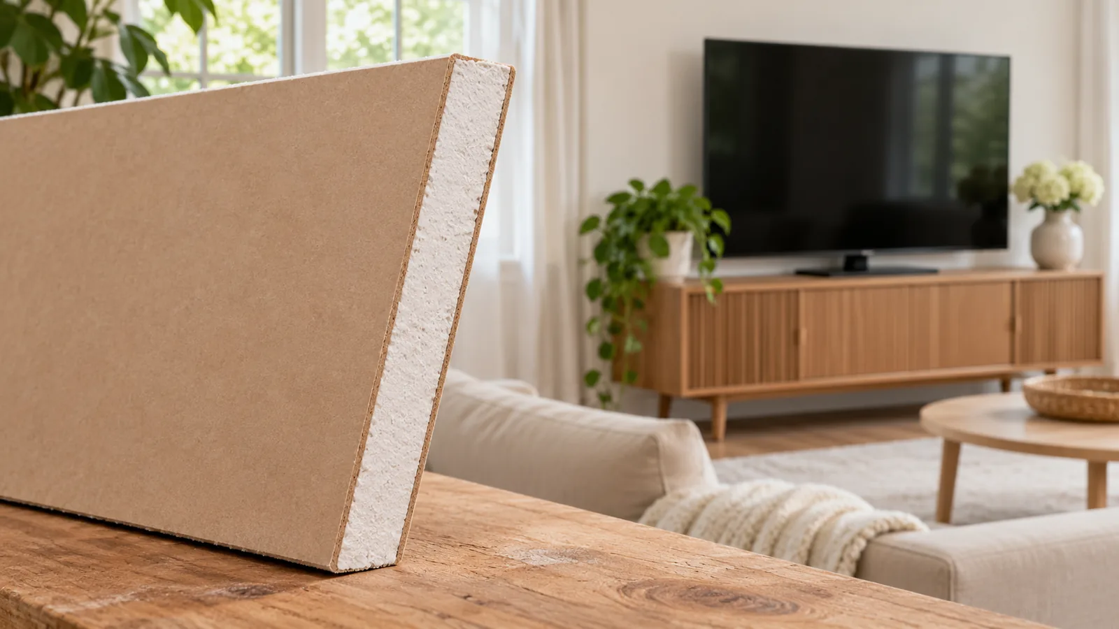
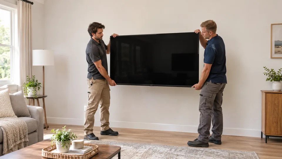
Make a cardboard outline using the TV's actual outside width and height, without its stand. Mark the screen center and hold the outline at the intended position with another person's help. Check the view from the far end of the sofa as well as the main seat. Include a soundbar in the mock-up if it will sit below or move with the screen.
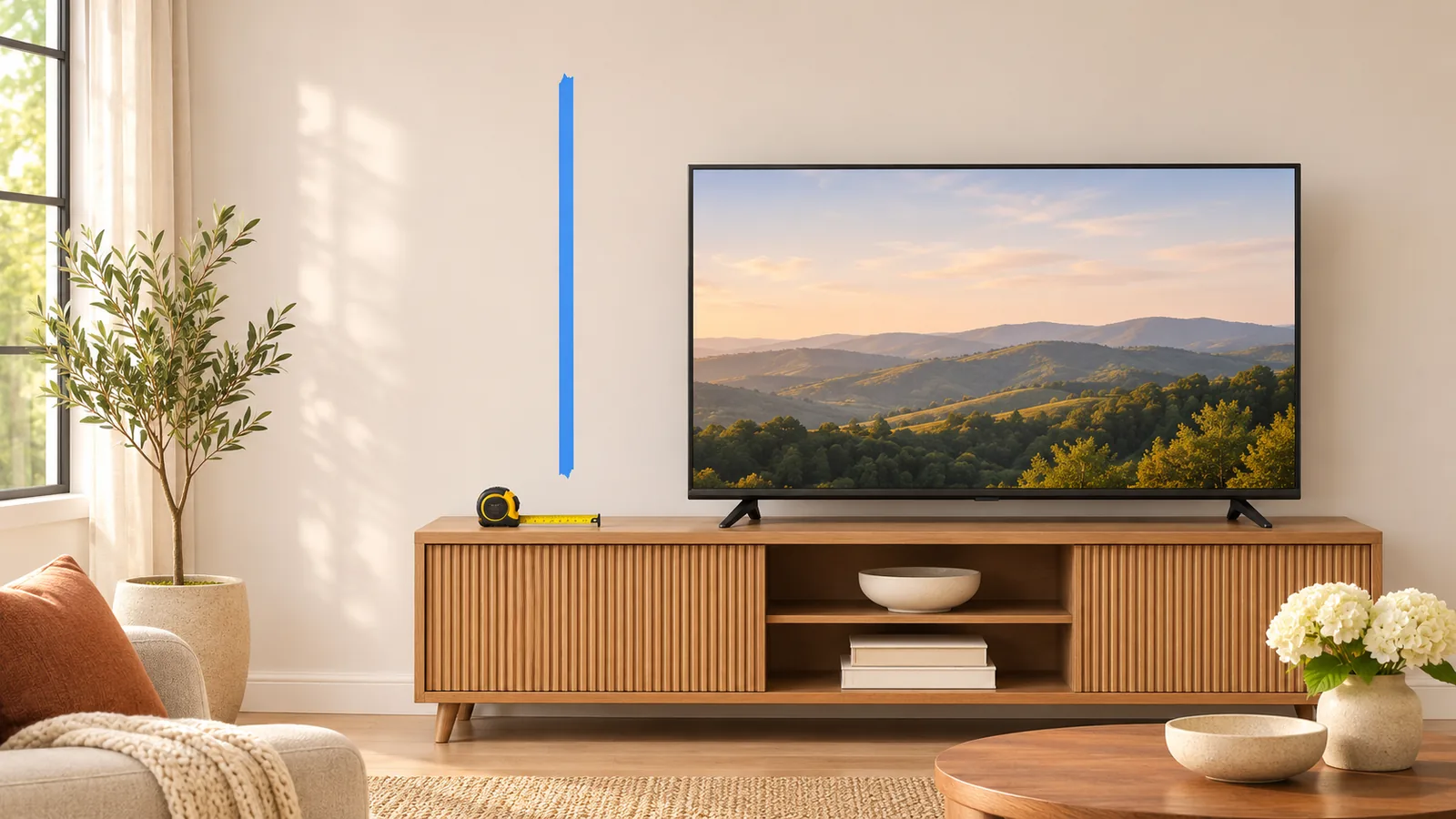
Set the vertical position independently of the corner geometry. Our TV mounting height guide explains how to start with seated eye level and translate that into a bottom-edge measurement. A corner installation is not a reason to raise the screen until its lower edge clears every piece of furniture; moving the furniture or choosing another wall may solve the conflict better.
Use the TV mounting height calculator to compare a proposed screen position. It helps with height planning; it does not verify the corner clearance, arm travel or wall support.
Understand the two attachment layouts
A single-wall articulating mount attaches to one of the two walls and extends the TV into the corner. A purpose-built two-wall corner mount has attachment plates arranged for both walls. These are different systems: a normal wall plate should not be bent, split, or improvised across a corner.
Kanto's corner-mounting guide distinguishes corner layouts and emphasizes weight, mounting-hole compatibility, and attachment locations. Use those as selection checks, then obtain the manual for the exact product. A single-wall model may need one stud or two; a two-wall model needs suitable attachment on both sides. The number of visible arms does not establish the strength of the completed installation.
| Layout | Useful when | What to verify |
|---|---|---|
| Single-wall articulating mount | One wall provides a suitable attachment location and the arm can reach the desired position | Wall-plate location, arm travel, folded offset, and clearance from the other wall |
| Purpose-built two-wall corner mount | Both walls can support the manufacturer's specified attachment | Approved corner geometry, both attachment locations, and the available adjustment |
| Another wall or a suitable stand | The desired corner has a doorway, unsuitable structure, or insufficient clearance | Viewing direction, furniture footprint, and the chosen product's installation requirements |
Measure clearance with a simple top-view calculation
The following is a planning example, not a mount specification. Imagine a very thin, 56-inch-wide TV centered symmetrically across a square corner at 45 degrees to each wall. Half its width is 28 inches. The projection of that half-width toward either wall is 28 × sin(45°), or about 19.8 inches.
That means the screen's center must be more than 19.8 inches from each wall just to keep an idealized zero-thickness screen from touching. If you choose 3 inches of additional planning space at each end, the center is about 22.8 inches from each wall. The center's distance along the corner bisector is about 32.2 inches, not 22.8 inches. These are different measurements.

The chosen 3 inches is an illustration, not a required ventilation or connector clearance. The real TV has depth, the mounting interface may sit behind the screen center, and plugs may protrude. Add the actual dimensions and the manufacturer's clearances before deciding whether a bracket works. An out-of-square corner or a different viewing angle changes the geometry.
Do not compare the 32.2-inch corner-diagonal measurement directly with a product's wall-extension number. Extension is normally described relative to the mounting wall and a defined part of the bracket or TV. Read the drawing to identify that reference. Then place the wall plate where the verified structure allows it and check whether the arm can reach the target position from there.
Apply the example to a real mount specification. ECHOGEAR lists the EGLF2 with 22 inches of extension. In its linked drawing, find the 22.02 in / 559.3 mm dimension under “Top view - extended” and follow the dimension lines to see what it measures.
In our sketch, the blue arrows run from each wall to the screen center; the separate 32.2-inch measurement starts at the room corner. In the idealized 56-inch-wide screen example above, the chosen center is about 22.8 inches from each wall. These numbers do not by themselves establish a fit: the mount specification and the screen-center calculation can use different reference points, and the TV has depth.
Use the EGLF2 dimension drawing, the actual TV dimensions and permitted wall-plate location to check the watching position, parked position and the path between them. If the dimensions or wall support cannot be confirmed, pause or select another layout.
Check the whole motion path
Maximum extension and maximum swivel are not a promise that both are available with your TV in your corner. For example, Kanto's FMC4 page makes swivel dependent on screen size and extension. SANUS's VLF728 page lists its own extension and swivel specifications. Those figures describe individual products; they do not transfer to other mounts.
Check the position used for watching, the position used when parked, and the path between them. Look for the screen edge approaching the return wall, an arm approaching the corner, the TV contacting trim, and a soundbar catching a cabinet. Stop before contact; forcing the arm can damage the installation or the TV.

Also check where the TV ends up when the arm folds. Some mounts shift the screen sideways as they retract. A wall plate centered on a tape outline may therefore leave the parked TV off-center. Vogel's positioning instructions illustrate why full-motion mounts can require model-specific horizontal offsets. Use your own mount's drawing, not another model's offset table.
Verify both sides of the mounting system
The TV side needs the correct mounting-hole pattern, compatible screws and spacers, and adequate weight capacity. VESA measurements describe the horizontal and vertical spacing between the TV's mounting holes, generally in millimeters. They do not specify every screw length or confirm that a mount clears recessed connections. Consult the TV manual as well as the bracket manual.
The wall side needs a permitted wall type and a compatible fastening method. A stud finder is useful evidence, but a signal on the wall is not a complete assessment of framing or hidden services. Do not replace a missed stud with a generic toggle because a package advertises a large load number. A specialized drywall system may have its own tested conditions; that does not authorize the same fastener with an arbitrary articulating mount.
If the corner is brick-faced, establish whether the brick is structural masonry or a finish over another assembly. The brick and concrete planning guide explains that distinction. Unknown backing, deteriorated material, or a wall not covered by the mount's instructions needs assessment before installation.
Plan cables and the final installation
Measure cable length with the screen in its farthest intended position. Then check that the spare length can fold safely when the TV returns. A cable can be long enough at full extension yet become trapped at an arm joint when parked. Follow the mount's cable-management route, avoid tension at connectors, and keep ventilation openings clear.
Power and signal cables need separate planning. An ordinary TV power cord stays outside the wall. A surface cover or an appropriate power-relocation system may suit the room; see the wire-concealment comparison. A room corner does not make a hidden electrical route automatically available.
Before installation, have the TV and mount model numbers, wall information, proposed center height, and clearance measurements ready. The installer can then verify attachment positions, fit the TV-side hardware to the existing threaded mounting points, and follow the specified fastening and locking sequence. Never drill new mounting holes in a TV casing.
If you want help with that plan, configure your TVMounty installation with the TV size and intended options. Address coverage and any travel fee are checked during booking, and a requested arrival window needs confirmation. Keep the cardboard outline until the final location is agreed; it is a useful way to explain what you want the finished position to achieve.